

Pumping and Hydraulics Solutions for Irrigation and Water Supply
ABN: 92 105 345 506
Pipeline Friction
Fluid flow creates internal friction in all pipe systems. This is the due to both the roughness of the pipe internal wall and the viscous sheer stresses of the fluid, collectively causing resistance to fluid flow.
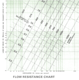
Pipe manufacturers quote friction losses for their pipes in complex charts called Flow Resistance Charts, an example as shown right.
This defines pipe internal resistance, usually expressed in metres head loss per 100 metres of pipe (or m/1000m) as shown on the left column and at a particular flow rate as shown across the bottom of the chart.
How is friction expressed?
Pipeline systems are designed around manufacturer quoted friction values so that they are hydraulically balanced in the system in which they operate.
Hydraulics Engineers have come up with various ways of expressing pipeline friction. They are:
Pipeline systems are designed around manufacturer quoted friction values so that they are hydraulically balanced in the system in which they operate.
Hydraulics Engineers have come up with various ways of expressing pipeline friction. They are:
Chart: Courtesy Hardie's Pipelines Systems, Hobas
The Hazen-Williams formula is preferred since it is easy to compute flow reductions due to increased pipe friction merely by applying the ratio of the changed C value. Eg, a pipe with head loss coefficient of C=100 reducing to C=80 will have a 20% flow rate reduction, given that all other conditions, including head loss in m/1000m, remain the same.
Pipeline friction alters over time.
Did you know that pipeline friction alters in time and can therefore affect the fine hydraulic balance so carefully assigned in the design process?
Did you know that pipeline friction alters in time and can therefore affect the fine hydraulic balance so carefully assigned in the design process?
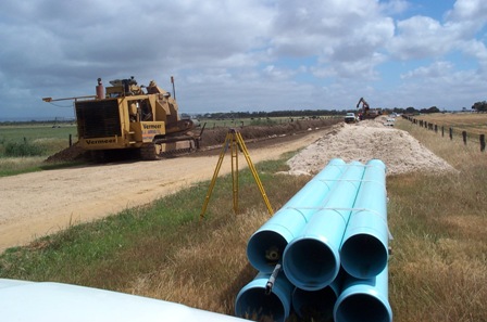
For example, a 500NB PVC pipeline was designed and built for pumping around 4GL/annum of recycled water over 10 km with a static lift of around 50m. After 1 year, there was a noticeable reduction in pumped flow rate.
Rob conducted a friction test on the pipeline and found that the Hazen and Williams Coefficient had changed from the design value of C=155 to C=135, ie an increase in pipeline friction of 15%. This had the effect of adding about $2,000 /annum to the pumping cost, not to mention the in-ability to supply peak water loads when required.
Rob conducted a friction test on the pipeline and found that the Hazen and Williams Coefficient had changed from the design value of C=155 to C=135, ie an increase in pipeline friction of 15%. This had the effect of adding about $2,000 /annum to the pumping cost, not to mention the in-ability to supply peak water loads when required.
Laying mPVC pipe, Langhorne Ck, SA Photo R Welke
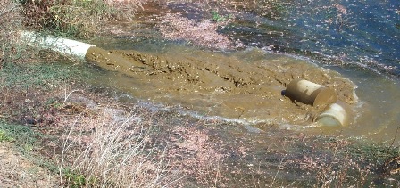
Pigging
A "pig" is a foam cylinder , slightly larger than pipe ID.
In the case above, the original pipeline friction values were restored with regular pigging to clean the inside pipe surface. The same effect could have been achieved with continuous chlorination, as in the case with potable water pipeline systems.
Chlorinated v's unchlorinated
A good cement lining will prevent corrosion of the inside of a steel pipe (MSCL) or cast iron pipe (CICL) and hence retain the pipes good flow qualities. However, even cement lining can build up with algae and suffer from increased friction losses.
In potable supplies, where chlorinated water keeps algae growth to minimum, pipelines tend to maintain their original C Value. However, excessive chlorination can leach lime from cement lining, leaving it frail and porous.
With un-chlorinated water, and especially recycled water for irrigation, algae growth can very quickly diminish a pipes performance in PVC, poly and cement lined pipes.
Pigging a pipeline: Note spent pigs on right, and dirty water which the "pigs" cleaned from the pipe Photo R Welke
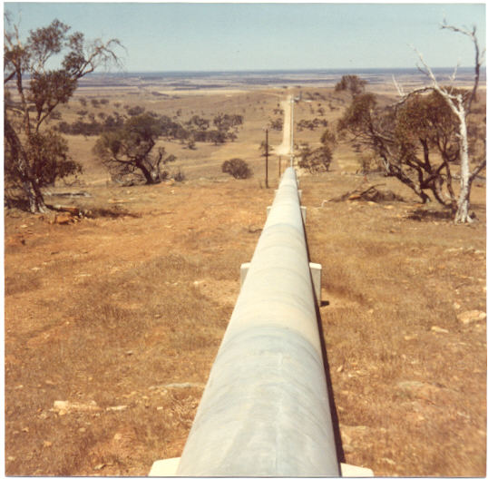
Swan Reach-Stockwell MSCL Pipeline, SA Photo R Welke
Snails
In un-chlorinated water supplies, especially irrigation from dams, rivers and lakes, pipelines can get a buildup up snails on the inside, resulting in huge C Value losses. Chlorination and pigging combination may be successfully applied to this problem.
Pipeline friction can be measured in the field and Rob has had extensive experience in pipeline friction testing.
Pipeline Maintenance
Pipelines and irrigation systems never stay new for long! In time, water impurities take their toll on pipeline friction and irrigation drip efficiency.
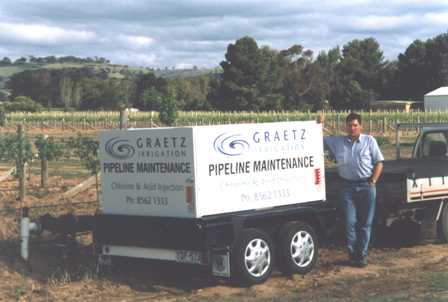
In 2000, Rob designed and built this acid injection trailer (photo right) for a Barossa Valley Irrigation Company.
The trailer holds 600 litres of either 35% Hydrochloric acid, or 600 litres of 12.5% sodium hypochlorite. The acid injector is computer controlled.
It has been used successfully to treat iron hydroxide build up in vineyard dripper systems and algae control in pipelines generally.
It is just one of the methods used to rehabilitate high friction pipelines and deteriorated dripper systems.
Pipelines and irrigation systems never stay new for long! In time, water impurities take their toll on pipeline friction and irrigation drip efficiency.
In 2000, Rob designed and built this acid injection trailer (photo right) for a Barossa Valley Irrigation Company.
The trailer holds 600 litres of either 35% Hydrochloric acid, or 600 litres of 12.5% sodium hypochlorite. The acid injector is computer controlled.
It has been used successfully to treat iron hydroxide build up in vineyard dripper systems and algae control in pipelines generally.
It is just one of the methods used to rehabilitate high friction pipelines and deteriorated dripper systems.
Contact Tallemenco to assist in the assessment of your pipeline system efficiency and determine exactly where your pipe friction losses are occurring.
Once the source of increased friction has been determined, Tallemenco can advise on remedial works to restore your pipeline to top efficiency again, potentially saving you thousands of dollars annually in pumping and operating costs.
Acid Injection trailer which Rob designed and built for rehabilitating high friction pipelines and clogged dripper systems.
Colebrook-White formula which expresses pipe wall roughness as a coefficient in the range 0.003 to 0.015mm
Darcy-Weisbach formula which expresses pipe wall roughness as a ratio between roughness (e) and pipe diameter (D), ie relative roughness.
Hazen-Williams formula which expresses pipe friction as a head loss co-efficient C, with typically "C" values ranging from C=80 for small pipes up to C=150 for large smooth bore pipes.
Tallemenco Pty Ltd, Windsor Gardens, SOUTH AUSTRALIA, 5087.
ABN: 92 105 345 506
Mobile 0414 492 256
Intn'l: Cell +61 414 492 256
Skype: robwelke
ABN: 92 105 345 506
Mobile 0414 492 256
Intn'l: Cell +61 414 492 256
Skype: robwelke
Last Update
Nov 8th 2019
Nov 8th 2019